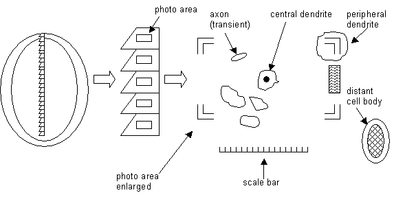
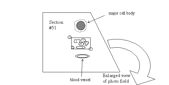
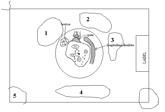
The aim in photographing serial thin sections is to maintain the same field of view from section to section. Having many, very tiny, consecutive sections on as few grids as possible, and the ability to rotate the grid to maintain orientation, makes this objective relatively easy. The other means of maintaining the same field of view is to identify the same entities from one photo field to the next. In a field of cross-sectioned dendrites, the easiest method is to keep the same dendrite in the center of the photo field from section to section. A perfectly cross-sectioned dendrite of 1 µm diameter, depicted by the perfect cross-section of its microtubules, is the current preferred central reference. In addition, other entities within the photo field are also identified and recorded. These are other cross-sectioned dendrites of various sizes that are more or less a constant feature throughout a series. Then there are the transient entities, e.g., axons, longitudinal dendrites, degenerated entities in the neuropil, etc., which are also useful too. We avoid including very large entities, such as blood vessels or cell bodies within or in the proximity of the photo field in the current research. These large structures are not of interest at all but are still useful as distant references within the series. See diagrams:
It is recommended to make drawings of a photo field, especially when moving from the end of one ribbon of sections to the start of the next ribbon. Otherwise, it is easy to forget the exact area. Also, one may wish to return to the exact location of photography of a series at some later date. It is also recommended to set up your notebook in the following way: include the negative #, grid #, section #, notes or comments.
Neg# Grid Sect# Notes________
AB0001 D1 16 folds in section
AB0002 D1 17 __________________
AB0003 D1 18 ____________
AB0004 D1 19 dirt in section
AB0005 D1 20 ____________
AB0006 D1 21 ____________
AB0007 D1 22 ____________
AB0008 D1 23 ____________
To proceed with serial photography:
- Ideally, one should first photograph each ribbon of sections at LOW MAG (50 to 200X) before shooting the series. The reason is that one can know ahead of time the disposition of the series and one can count exactly how many sections there are. Oftentimes there are problems with some sections in a series, e.g., folds, cracks, staining artifacts, etc. One can have the low magnification negatives and/or photographs in hand while plotting the best areas of the troubled sections to shoot. If there are too many problems to circumvent, then discard the series based on the low magnification evidence.
- If it is not practical to do this pre-photography of a series, then it is still necessary to pre-view each ribbon at low magnification for several minutes prior to high magnification photography, for the following reasons:
- The entire grid surface is exposed to low electron beam energy simultaneously. This “baking out” of the sections and the Pioloform film at low mag seems to result in a more stable image at higher mags. Consequently, there is less image drift.
- Section quality can be ascertained. The consistently best areas, from section to section, could still be mapped out.
- The number of sections present in a ribbon can be determined.
-
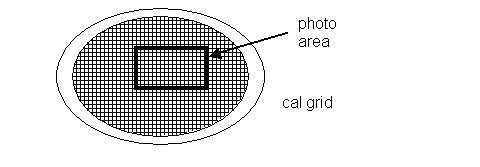
It is also important to photograph the calibration grid along with shooting a series. One can shoot it before or after the series. The calibration grid (Ernest Fullam, Inc., cat# 60021 or #10021) is photographed at the same magnification as the series, e.g., 10,000X, and is used for later calibration of image size. See Fiala & Harris, 2001 for an in depth description. Note the appearance of the cal grid as a meshwork of vertical and horizontal lines, spaced equally apart. Orient the grid via rotation so that the lines are as vertical and horizontal as possible for photography. See diagram:
Then photograph the grid, following the procedures in steps 11 and 12.
- Remember to adjust each grid for proper Z alignment. See the electron microscope alignment protocol for this procedure. Do the Z alignment on an area of the Pioloform distant to the series sections to avoid any beam burn.
- Begin to shoot the series from a section located in about the middle of the series. Rotate the grid as needed to properly orient the section. Work under low beam exposure for now in order to avoid burning the sections.
-
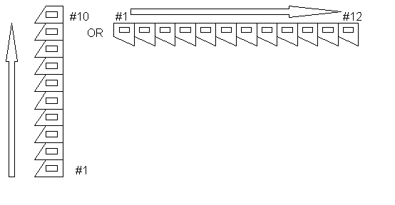
Decide how the series is to be photographed. For example, orient the ribbon vertically or horizontally via grid rotation. This, in turn, will dictate the orientation of the rectangular photo field. See diagrams:
-
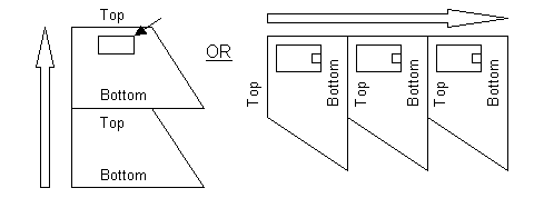
Starting with section # 50, for example, align the straight edge of the rectangle (either width or length) to the top or bottom edge of the section, as parallel as possible. Do this type of alignment with each section in the series. Rotate the grid as needed to obtain a good alignment. See diagram:
- It is recommended to photograph this particular section or even the first or last section of the series as a record. That is, photograph the entire section or at least as much of it as possible, at 1000X to 1500X. Then, after the entire series is photographed, it is possible to find the exact series photo field on the 1000X low magnification photo!
-
Select an area for serial photography, based on the research objectives. Avoid the extreme edges of the section because
- The edges are unstable and tend to shrink back under the beam.
- Due to the pyramidal shape of the trapezoid, anything located on the edges will be lost as the sections gets smaller in size, when going from section #50 to section #1.
Find a perfect cross-sectioned 1-µm dendrite as a central reference dendrite and position the center of it on the black dot on the small phosphorescent screen. Use the scale on the screen to measure the dendrite. At 10,000X, the length of the scale on the phosphorescent screen equals 5 um. From here on, this dendrite will be positioned in the center of the field, in the exact way for all sections in the series. The shape of the dendrite can change, from round to oval and back again, every few sections. In addition, the dendrite will have spines appearing, and then disappearing. The most constant feature of the cross-sectioned dendrite is the cluster of microtubules. Therefore, position the black dot of the screen in the center of this cluster!
-
Note the surrounding entities within and just outside the photo field. Draw this field, with as much detail as possible, along with any major entities outside the field, in the research notebook. These drawings serve as a map to find one’s way back to the photo field, if lost! See diagrams:
- When ready to photograph this field, observe if there is any image drift. If there is some drift, then wait a few minutes to allow film stabilization under the electron beam. Then proceed to photograph the field. Remember to focus the image, set the under-focus if appropriate, set the brightness exposure to 0.5 sec. Continue to wait for image drift to cease if necessary. Then shoot the photo.
-
Move on to the adjacent section, either section #49 or #51, depending on the direction chosen. Follow these procedures:
- Align the top/bottom edge of section to edge of rectangular photo field. Rotate grid as needed.
- Find the area of photography. One can measure how many photo fields or µm the photo field is located, relative to the section edge. And/or one may recognize the photo field from major landmarks. Center the central dendrite in the photo field. Remember that you are following the same central dendrite from section to section!
- Prepare to photograph the field. Focus the image, set the under-focus, set the exposure to 0.5 sec, wait for image drift to cease if necessary, and then shoot the photo.
- Repeat this procedure, until all sections on a grid are photographed.
If continuing on to an adjacent section on the next grid, be sure to draw the photo field of the last section photographed. This is necessary as one can forget the location of the field. Also, make drawings if there will be interruptions in the photography, such as in changing film plates, adding liquid nitrogen to the cold trap, coffee breaks, etc. Remember also to do the Z alignment on each new grid.
- Remember to photograph the calibration grid, either before or after shooting the series! The calibration grid tends to get damaged under prolonged electron beam exposure. Always search for an intact area of the calibration grid to shoot. Otherwise, have plenty of back up calibration grids to rely on.