Using the Vibroslicer, VT 1000S for Whole Brain and Sliced Brain
The procedure for operating the VT 1000S Vibroslicer will be described in this chapter, using the rat whole brain and rat transverse hippocampal slices as specimen samples. Many of the diagrams are copied directly out of the “Operating Instructions for the Leica VT 1000S” manual, English version, October 1996.
Materials: VT 1000 S Vibroslicer (Leica, Bannockburn, Ill), aldehyde-fixed whole rat brain or sliced brain, 0.1 M phosphate buffer, small artist’s brushes (Winsor-Newton, Talcon series 233, size 000), new double edged razor blades, Krazy Glue pen or gel, 70% ethanol, Kim-wipes, 20 ml scintillation vial, hemostats, scissors, glass Pasteur pipette (VWR Scientific, cat # 14672-200), polystyrene well plate (24 wells e.g.,)(Fisher Scientific, cat # 087721), the manual of “Operating Instructions for the Leica VT 1000S” as a further reference, lab coat or apron, gloves, safety glasses.
Procedure:
To begin a Vibroslicing session, the specimen is always placed in the instrument first, followed by the insertion of the knife. At the end of the cutting session, the knife is removed first, and then the specimen is removed.
1. Turn on the main power switch, located on rear, left side of Vibroslicer.
2. Mount the buffer tray onto the bolt inside the cooling bath receptacle of the VT 1000 S. Secure the buffer tray by flipping the clamping lever over to the right.
3. Lower the buffer tray/stage to its lowest position by toggling the UP/DOWN switch from its central position to the DOWN direction (black toggle switch located on main panel). To stop the audible signal when stage reaches bottom, raise the stage back up a bit until signal stops. Next, retract the knife holder arm to the rear as possible by toggling the REV/FORW black switch from its central position to the REV (reverse) direction. The last person to have used the Vibroslicer should have reversed the knife holder and lowered the stage as part of protocol, but don’t always count on it!
4. One can fill the cooling bath with crushed ice, if desired. Then fill the buffer tray with buffer, about ¾ full. This tray is auto-clavable. It can be stored overnight, filled with buffer, in a 4 degree C refrigerator, if so desired. Separate trays can be purchased and reserved for different buffer types.
5. Prepare to glue the specimen onto the rotating specimen holder: WORK AS QUICKLY AS POSSIBLE TO PREVENT THE TISSUES FROM DRYING OUT!
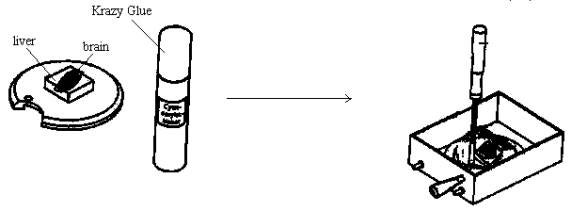
a) One approach is to first glue down a square piece of rat liver (approximately 1 cm x 1 cm x 1 to 2 mm) to the center of the rotating specimen holder. Then glue down the ventral aspect of the rat whole brain or one hemisphere to the liver square. In this way, most or all of the rat brain can be sliced. Or, if only the topmost slices of the brain are needed, then glue the ventral aspect of the brain directly onto the rotating specimen holder. Use as little glue as needed to do the job. Otherwise, too much glue will seep up into the tissue. To do the gluing, just place a few drops of Krazy Glue onto the center area of the holder. The holder should have been previously cleaned and dried from the last use. To dry any tissue surface for gluing, gently dab with a Kim-wipe, just enough to remove excess fluid. DO NOT OVER-DRY! . Next, place the intended surface, e.g., the ventral side of the brain, atop the glue. Add a few drops of buffer to the brain to keep the surface moist. Then, quickly screw in the manipulation tool into the screw hole of the holder. DO NOT OVERTIGHTEN!!! Then, transfer the holder into the buffer tray, using the tool as a handle. MAKE EVERY EFFORT TO GET THE TISSUE INTO THE BUFFER BATH AS SOON AS POSSIBLE!!! See diagram:
b) Another approach is to add a wall of agar behind the brain or brain/liver. To do this, glue down a pre-formed small block of agar, just behind the tissue. See diagram:
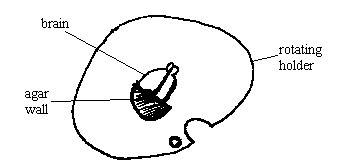
This will support the tissue as it is being sliced. THEN TRANSFER THE HOLDER INTO THE BUFFER TRAY. The semi-circular shape of this agar wall was made by pouring 4% or 7% liquid agar into a 50 ml polypropylene centrifuge tube (Corning Costar, VWR Scientific cat # 21008-690). Then cap it and allow it to harden overnight at 4 degrees C. Then cut off the pointy end of the tube. Uncap the tube and manually push out a short length of agar, about 3 to 4 mm, and slice it off with a razor blade. Then bisect it into two semi-circles. Cap the rest of the agar in the same tube and store it at 4 degrees C for future use.
c) Still yet another strategy is to embed the tissue in 4% or 7% agar. First, prepare a round support band, made either of polypropylene plastic or from paper or plastic tape. This band will encircle the rat brain as melted agar is poured in to cover the brain. To make the band from polypropylene plastic, use a single-edged razor blade to cut off a 2 to 2 ½ cm length from the open end of a 50 ml centrifuge tube. This is the same type of tube from step b. If using tape, then tape two ends of a short length of tape together to form a band, about 3 cm in diameter. The height of the band should be from 2 to 2 ½ cm.
Next, place the rat brain dorsal side down, on a glass microscope slide. Place the band around the brain. Add liquid agar (temperature ~ 45 to 50 degrees C) to the brain to completely cover it to form a high mound (about a few mm over the height of the band) Place a second glass slide on top of this mound to flatten it. The slide should then rest on the band for support. See diagram:
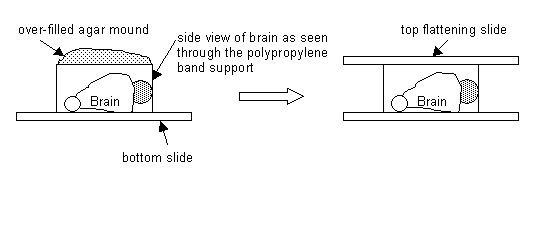
Next, place these glass slides with brain/agar into the refrigerator (4-degree C) for 5 to 15 minutes to harden. Then remove from refrigerator. Remove glass slides from brain/agar mold. Remove tape carefully. For the polypropylene plastic band, carefully push the brain/agar mold out. Next, a few drops buffer to brain/agar to moisten it.
Next, place a few drops of Krazy Glue to the center of the rotating stage holder. Then place the flat top of the agar, which is the ventral side of the brain, on the glue of the holder. In this position, the dorsal brain surface will be cut first. Then, quickly transfer the holder into the buffer tray.
d) There are yet other ways to agar mount tissue onto the specimen holder and these will be described later.
6. Once the tissue/holder is sitting in the buffer bath, prepare to secure the holder into the buffer tray:
a) Note that the semi-circular gap in the holder fits over the clamping screw in the buffer tray. Note also that the specimen holder must be seated under the two rear clamping posts. See diagram:
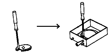
b) Use the tool to rotate the specimen holder, either clockwise or counterclockwise, in order to best position the tissue, as it will face the knife. The holder must be seated under the rear posts and the clamping screw. Align the holder so that the gap is not facing the posts or the clamping screw. Then, tighten the clamping screw with the 3 mm Allen key. DO NOT OVER-TIGHTEN THE CLAMPING SCREW!!! See diagram:
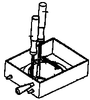
c) As soon as the specimen holder is tightly secured, then unscrew the manipulator tool.
d) Just as a note: More than one specimen could be mounted onto the specimen holder. So then, after one specimen is sliced and removed, the holder can be rotated to position the second tissue for slicing. See diagram:
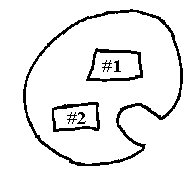
7. Prepare to load a razor blade into the knife holder.
a) First, break a new double-edged razor blade in half. Either use a dedicated scissors to cut it lengthwise down the middle of the blade or carefully bend it in half to break it. The other approach is to use either one or two hemostats to hold the blade and then bend it in half to break. AVOID TOUCHING THE ACTUAL BLADE CUTTING EDGE, AS ANY CONTACT COULD SCRATCH OR DULL IT!!! Prepare as many blades as described as needed. Use a new blade for each tissue specimen.
b) Clean the blades with a Kim-wipe and 70% ethanol. Then store the blade halves in a 20 ml glass scintillation vial or any appropriate container, for future use.
c) Another method of cleaning and storing the blades is to place all blade halves into the 20 ml scintillation vial or any appropriate container. Add 100% acetone to the vial and store until needed. On the day of cutting, remove one blade and clean it with a Kim-wipe and 70% ethanol.
d) Before loading a blade into the knife holder, check to see what the clearance angle is currently set at. The three major settings are 5, 10 and 15 degrees. See diagram:
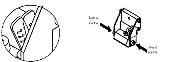
Generally, the clearance angle is left at 4 to 5 degrees, whereby only the topmost hole on the adjusting lever is fully visible. See above diagram. This is considered the smallest clearance angle. This particular setting is good for cutting thinner brain sections. To change the clearance angle, loosen the two lateral screws with the Allen key. Do not unscrew completely! See diagram above. Then use the adjusting lever to adjust to the desired clearance angle. Then, secure the selected clearance angle by adjusting the two lateral screws.
e) To insert a new, cleaned razor blade into the knife holder, loosen the clamping screw located on top of the upper clamping jaw of the knife holder. See diagram:
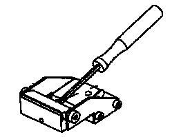
f) Examine the blade for any nicks or scratches. Discard if any seen. Select a better blade.
g) Hold the blade half at its two ends, between the thumb and forefinger. Then insert the broken edge into the knife holder. Secure the blade in the knife holder by lightly tightening the clamping screw. The blade should be loose enough to manually extend it from 1 to 5 mm or long enough to cut through the brain (specimen). Also, position the blade parallel to the front edges of the clamping jaws. Then, secure the blade completely with the clamping screw. See diagram:
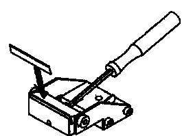
8. To mount the knife holder onto the Vibroslicer: Carefully, position the knife holder against the knife holder arm, without bumping into the mounted brain tissue. Then, secure with knife holder clamping screw. See diagram:
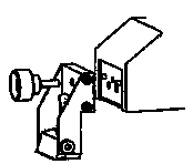
The knife should sit to the rear of the specimen. See diagram. Be sure that the level of the buffer solution covers the entire razor blade extent.
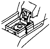
9. Prepare to set the cutting parameters for the particular specimen. See diagram of the main panel:
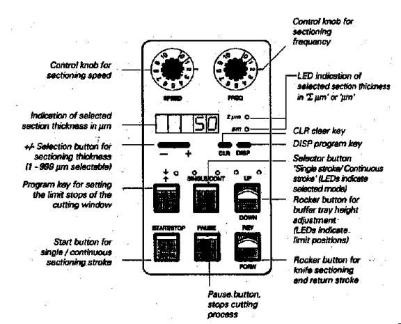
a) Select the sectioning speed and sectioning frequency with the control dials labeled SPEED and FREQ. See page 12 in the manual for the entire list of speed and frequency settings available for the Vibroslicer. Generally, a slow speed, about 1 to 2 on the dial is preferred. This is equivalent to 0.10 to 0.20 mm/sec speed. For frequency of blade oscillation as it cuts through the tissue, a high frequency is preferred. The suggested setting for soft tissue is 6.0 to 9.0 on the FREQ dial, which is equivalent to 60 to 90 Hertz.
b) To select a section thickness value, select from 1 to 999 μm by pressing the small gray oval bar marked – or +. This selected value is displayed on the panel.
c) To start a single stroke, first press the SINGLE/CONT button so the left light illuminates. Then press the START/STOP button. One forward and then one return stroke will occur. To initiate continuous cutting strokes, press the SINGLE/CONT button again so that the right light illuminates. Then press START/STOP button to initiate continuous cutting at the set speed and frequency. To stop the action, press START/STOP button and the knife will complete its stroke and return to the rear position.
d) There is also a PAUSE button to immediately interrupt the knife movement. Then press PAUSE again to resume knife movement.
e) To raise the brain specimen to a level below the knife (about 1 mm distance), look through the overhead stereomicroscope (if useful) and toggle the UP/DOWN switch to the UP direction. Slowly raise it in increments. You may have to advance the knife forward a bit and suspend it over the specimen first. This may give you a better perception of how high you need to raise the specimen holder stage. To advance the knife, toggle the REV/FORW switch in the FORW direction. To retract the knife, toggle to the REV direction. To lower the specimen, toggle the UP/DOWN switch toward the DOWN direction.
f) The REV/FORW function has other uses. The tissue can be cut manually in this mode. The FORW motion continues only as long as the toggle is held in FORW direction. In contrast, the REV motion is carried out completely, once the REV function is initiated. To stop the REV movement before reaching the rear, switch back the toggle to its center position.
g) There is an EMERGENCY STOP BUTTON, located on the right side of the Vibroslicer. It is red and has a white circular arrow on it. If it is necessary to stop the cutting procedure immediately, then press this EMERGENCY button. To resume cutting, unlock this button by turning it in the direction of the arrow.
h) Set the length of the cutting window. Here, you are setting the length of the cutting stroke as it passes through the extent of the specimen, from the rear to the front. Before doing this step, make sure the knife level is a safe distance above the tissue to avoid any collision!!! The first step, then, is to position the knife to about 1 to 2 mm to the rear (1) of the specimen and/or agar frame, using the REV/FORW toggle. Then, press the button to activate the cutting window. This button has the symbol of opposing arrows above it. The LED flashes once. You have now set the rear limit (1) of the cutting stroke. See diagram:
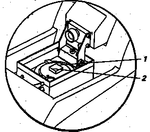
The second step is to set the front limit (2) of the cutting stroke, using the REV/FORW toggle. Advance the knife to extend about 1 to 2 mm in front of the tissue or agar frame. Then, press the button for the cutting window. The LED flashes once. To check the adequacy this cutting window, turn on the SINGLE stroke or CONTINUOUS stroke-cutting mode. If the cutting window is too short or too long, then reset the limits on the cutting window as just described in this step. The length of the cutting stroke should encompass the entire breadth of the tissue, and some or all, of the agar frame, as desired. In addition, the length of the cutting window should include a safe margin 1 to 3 mm beyond the tissue/agar area.
i) In regard to the amplitude adjustment, the current setting of 0.4 mm seems to work satisfactorily for soft tissues.
This covers approximately all of the control settings for cutting the specimen.
10. Prepare to cut the specimen:
a) Look through the stereomicroscope and adjust the fiber optic lights as needed.
b) Start the cutting process by pressing the START/STOP button. Observe that the first few cutting strokes should yield nothing as the knife travels above the specimen level. With each cutting stroke, the stage is being raised so many microns.
c) Once the knife contacts the tissue, you may then wish to allow the cutting to continue until a certain depth in the tissue is reached. Then you may choose to start collecting only the deeper level sections. Or, you may opt to save all the sections.
d) When enough sections are cut, turn off the instrument by pressing the START/STOP button. Or, if the exact sequence of sectioning must be maintained, and more time is needed to pick up one section at a time, then stop the Vibroslicer after each section is cut.
e) Pick up each section carefully, with a brush or some other appropriate instrument. Then, transfer the section to a well that contains buffer or to some other appropriate container. Or, if you can work quickly enough, pick up the sections as they are being cut without turning off the Vibroslicer.
11. At the end of the cutting session, proceed as follows:
a) Lower the stage as low as possible. Retract the knife as far back as possible.
b) Remove the knife holder.
c) Carefully, remove the blade from the holder.
d) Remove the specimen holder.
e) Remove the specimen and any glue residue from the holder by scraping it off with the razor blade. Try not to scrape the painted covering. Dispose of the blade in the sharps container. Rinse the holder well with water. Pour this rinse water into waste aldehyde container. Then clean the holder with 70% ethanol and a Kim-wipe. Dry with a Kim-wipe.
f) Remove the buffer tray and then drain the buffer into the appropriate waste container (for aldehyde wastes). Rinse it several times with water. Drain rinsing water off into the same waste container. Rinse the tray with water and then wipe dry.
g) Clean all tools and surfaces that came in contact with the buffer by rinsing well with water. This includes the control buttons on the Vibroslicer, all surfaces of the Vibroslicer, the near-by counter-top, etc. Dry with Kim-wipes or towel paper.
h) Drain the cooling bath, if used. The drainpipe is located on the right rear of the Vibroslicer. To drain the bath, loosen the end of the drain tube. Drain the bath into a beaker or other container.
i) Switch off the main power to the Vibroslicer.
j) Cover the Vibroslicer with plastic dust cover.
Some additional techniques for the Vibroslicer:
1. Once a certain slice thickness, e.g., 400 μm, has been cut on the Vibroslicer or with the Stoelting tissue chopper, then this slice can be re-mounted in agar and cut into even thinner sections, e.g., 40 μm. To do this:
a) From the 400 μm brain slice, e.g., use a scalpel to cut away surrounding tissue to isolate a smaller region of interest. Keep tissue wet by adding drops of buffer to it.
b) Construct a mounting stage from glass microscope slides. This can be re-used many times. To do this, position two glass slides (25 x 75 x 1 mm) parallel to each other, at least 26-27 mm apart. Then, place two more of the same type slides across the ends of the original slides. Then glue the ends together with a strong glue. Allow the glue to harden. See diagram:
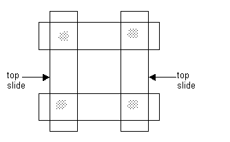
One or more set of slides can be glued directly on one of the sets of slides, as long as they are completely covering the slides. This will add more height to the agar mounting stage. See diagram:

c) Place the tissue on one of the lower glass slides. Place that surface of the tissue, which will be cut first in the Vibroslicer, facing down on the glass slide. Then place 7% liquid agar (temperature about 45 to 50 degrees C) atop the tissue to completely cover the top and sides of tissue. Build up a mound of agar from 1 to 3 mm, or as high as needed. See diagram:

d) Place a glass slide atop the agar mound, while the agar is still soft, to flatten the top 1 to 2 mm of it. Next, place the glass stage on ice or in a 4 degree C refrigerator for 5 to 10 minutes, in order to harden the agar. Add drops of buffer to agar to keep tissue moist.
e) Remove the glass stage from the cold. Then remove the glass flattener slide. If desired, trim the agar/tissue mount a bit to a square shape.
f) Pick up the agar/tissue mount with a small metal spatula or appropriate instrument and transfer it over to the area of the Vibroslicer. Glue the agar bottom of the mount to the dry surface of the specimen holder stage. See diagram:
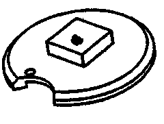
g) Keep tissue moist by adding a few drops of buffer to it. Transfer the specimen holder into the buffer tray as described in step 5a.
h) The tissue is now ready for Vibroslicing.
i) Any small tissue can be mounted in this exact way, including the entire ant brain.
2. An alternative approach to avoid dealing with the all the surrounding agar frame, is to make some fine scalpel cuts around the tissue as follows:
a) Very carefully, make a square or rectangular cut into the agar, immediately surrounding the tissue. Or just make three cuts. One can do this as the tissue/agar sits in the buffer tray. See diagram:
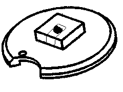
b) Set the length of the cutting window to encompass the length of the tissue and 1 to 2 mm beyond, into the agar frame.
c) Set the cutting speed to less than 1 on the SPEED dial.
d) Set the frequency to 6.8 on the FREQ dial.
e) Start the Vibroslicer to cut in the CONTINUAL stroke mode until it looks like the tissue level is about to be reached. Then STOP the Vibroslicer and resume cutting in the SINGLE stroke mode.
f) As the tissue is being Vibrosliced, the critical section will tend to float up and away from the rest of the agar mount. Stop the Vibroslicer as soon as this small section is cut while the knife is still in the FORW movement. Pick up the floating section with the opened end of a glass Pasteur pipette (diameter approximately 5 to 6 mm), gently aspirating it up into the pipette barrel.
g) Transfer the section to an appropriate well containing some buffer.
h) Turn on the instrument to resume cutting the rest of the agar mount.
i) Repeat this procedure until all sections are cut, in the SINGLE stroke mode of cutting.